Linear Light Path Flow Cell Construction
LLP flow cell will enhance sensitivity of spectrophotometric measurement up to 100x, since its light path can be up to 100cm long. Its key component is 0.8mm I.D. green PEEK tubing , with ends cut at 45-degree angle, sandwiched between two 0.5mm O.D. quarts fibers, encased in the same type of green PEEK tubing. This construct ensures perfect optical coupling and unobstructed flow, between the fibers and internal volume of flow cell. LLP flow cell is a collimator (not Liquid Core Waveguide) and therefore its optical path must be kept straight by external supporting tube. It can be fabricated in any length, tailored to desired sensitivity by using inexpensive components.
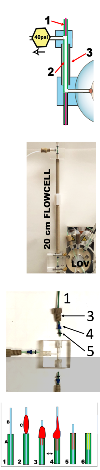
The LLP flow cell is comprised of the following parts: 1) The flow cell body (2), made from PEEK tubing 0.8mm I.D. internal volume 5microliter/cm.
2) An external rigid tube (3).
3) An inlet and outlet fitting.
4) Two optical fibers (1) which have one end cut square and polished, while the other end is terminated in an SNS connector that is coupled to the light source or the spectrophotometer. It is recommended to use optional 40psi flow restrictor to prevent formation of air bubbles.
The following components were used:
Green PEEK tubing (1/16” O.D. (1.6mm) x 0.03” I.D. (0.8 mm, IDEX Health & Science, LLC, Oak Harbor, WA, USA) was cut at a 45o angle at the required length. When mounted it was tightly sandwiched between the flat ends of two optical fibers, mounted in the outlet and inlet “T” pieces. The PEEK cell tubing (O.D. 1.6 mm), was housed in and held straight by a rigid tubing of I.D. 2 mm, screwed into end T-pieces.
This construct was made leak free by using following fittings and O-rings:, 1 – optical fiber, 2- waste line, 3- flangeless nut, 4- flangeless ferrule, 5- O ring. (flangeless nut, P-230, IDEX Health & Science, LLC, Oak Harbor, WA, USA), ferrules (Flangeless Ferrule Tefzel™ (ETFE), P-200X, IDEX Health & Science, LLC, Oak Harbor, WA, USA) and O-rings (#003 Buna-N O-Ring).
The optical fibers were made as shown below where A-PEEK tubing, B- Optical fiber, C- two component epoxy glue. Optical fiber used was Silica Optical Fiber FV 600 core, 660 clad, 710 buffer by Polymicrotechnologies, and was encased within the PEEK in the following way:
Cut 100cm of green PEEK tubing (A) and 120cm of optical fiber.
1. Insert fiber (B) into the tubing.
2. Mix two component epoxy glue and apply as shown (C).
3. and 4. Move fiber several times 2 to 3 cm back and forth to bring the glue inside the tubing as shown.
5. Wipe ALL glue from the outside of the tube and fiber. Let cure.
6. Cut square the extending fiber and polish the end. On the other end of the fiber attach SNS connector.
1.4.12.


M. Hatta, J.Ruzicka, Ch. I. Measures "The performance of a new linear light path flow cell is compared with a liquid core waveguide and the linear cell is used for spectrophotometric determination of nitrite in sea water at nanomolar concentrations" Talanta, 219, Nov. 2020 121240